Abstract
In today’s world, more electricity is consumed due to street lighting. This is due to the continuous operation of lighting during the night. To reduce power consumption and energy waste, a system must combine the existing network with intelligence so that it can think for itself. This newly developed concept enables street lights to automatically adjust based on real-time traffic conditions and change according to natural conditions (full moon). This paper deals with the development and implementation of low-cost sensor-based street lights, which in turn reduce energy consumption and CO2 emissions. This system includes IR sensor, PIR sensor, low cost embedded controller and storage device.
Introduction
Electricity is one of the common demands of people in the world, although it can be produced, but it does not meet the exact need. To overcome this, electricity must be saved during non-use hours, and it is very difficult for humans to monitor and control it. In today’s world, 60% of the electricity produced is spent on street lighting due to its continuous operation at night. To minimize power consumption, rich technology should be used for street lighting system. This paper discusses a dynamic street lighting system that reduces energy waste and CO2 emissions. This system intelligently adapts lighting levels based on weather conditions and traffic density. These levels or intensity of illumination are dynamically adjusted through sensors and microcontrollers according to the line current density. An external feature is also included in the system, so that the street lights adapt the lighting based on natural features such as full moon conditions, and the lights only shine at half their natural intensity.
Smart street light architecture

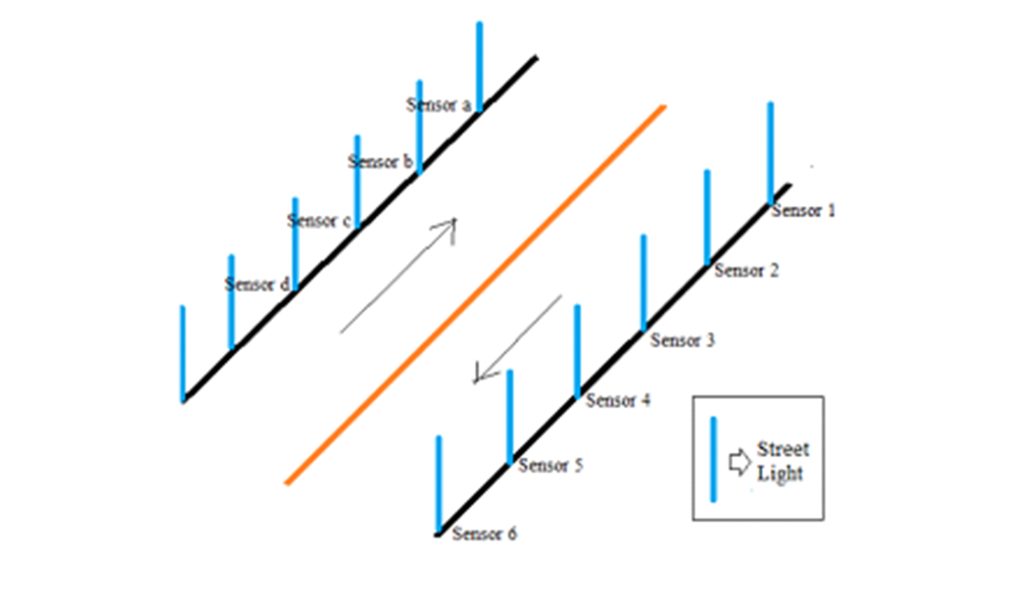
Figure 1. IR and PIR sensors in Lane
This architecture consists of several IR and PIR sensors placed at both ends of the line to detect the density of passers-by. These sensors are placed at a certain distance and transmit information when the vehicle is detected. The sensors communicate with each other through a wired connection. Here, wired connection is used to reduce the cost. Implementing smart street lighting and dynamic street lighting provides an easy way to reduce energy consumption and CO2 emissions. This system has the ability to control the flow in real time. Each sensor section consists of both infrared and PIR sensors for current detection. Here these two sensors are used to improve its detection accuracy. These sensors are connected to the microcontroller where the data is processed and adjust the lighting levels. Whenever a passerby is detected by the sensor, it communicates with the nearby street lights and turns on the surrounding lights. When no activity is detected, the street lights dim to a low voltage level and turn on to a high voltage level when motion is detected. Due to the progress of industries, this system will play a major role in saving electricity consumption without affecting comfort. Figure 1 shows the schematic diagram of dynamic street lighting system with IR and PIR sensors in line.
Block diagram of dynamic street lights
Figure 2 shows the block diagram of the dynamic street lighting system. The block diagram consists of different subsystems such as sensing unit, microcontroller unit and lighting system. The sensing unit consists of both IR and PIR sensors to detect line density. A low-power microcontroller is connected to the sensor unit to adjust the level of illumination intensity based on the density. The microcontroller is connected to the lighting system. The whole unit is powered by batteries. The sensing unit makes internal connections to clear the lights along the way.

Figure 2. Basic block diagram of dynamic street lighting system
Street light detection and control
۳.۱ unit of diagnosis
The detection unit consists of infrared sensors and passive infrared sensors on each side of the line, which detect line congestion or current and send the data to the microcontroller for processing. These sensor units are placed on both sides of the road for separate operation on each side. These sensor units communicate with each other during its operation. When a person is detected in the lane, the unit turns on its lights, as well as the adjacent lights, so that the person can be surrounded by a safe circle of light. This is achieved due to communication between sensors. This dynamic control of street lights overcomes the wastage of electrical energy which is most required in today’s energy crisis. In this dynamic control, the detection unit plays an important role to sense the line density and take the corresponding actions through the microcontroller.
۳.۲ Street light control through calculations
From the sensor unit, the data is transferred to the microcontroller in which the dynamic control of the
street light is performed, whose flow diagram is shown in Figure 3.

Figure 3 Flow chart of dynamic street lighting system
The flow diagram explains the lighting control in dynamic street lighting system. At first, all values related to density are read through the measuring unit. It first checks if there is any movement in the line, and then splits into two subsections.
I. If there is any motion data, the lights will shine at their higher brightness and communicate with the nearby sensor to turn on the surrounding lights.
II. Otherwise, the lights shine at a quarter of their original brightness and communicate with neighbors to perform the same operation.
Therefore, the system allows high brightness for higher density and lower brightness for lower density. A line with lower condensing current saves electricity consumption for the future and reduces CO2 emissions. Street lights counter control system is also included in this system. The counting operation is done in the microcontroller itself. There will be a full moon day every 30 days. The counter is made so that whenever the counter reaches a multiple of 30, the light will decrease to 25% of its original brightness. The implementation of this system in the city leads to 60% saving in electricity consumption and as a result reducing CO2.
- Test setup
۴.۱ Density detection
The sensors are placed at both ends of the road. It consists of infrared sensor and passive infrared. These sensors are used to detect line congestion. These sensors give a digital output that is either 0V or 5V depending on the detection. Suppose if movement is detected in a certain line, it outputs 5 volts, otherwise the output voltage is 0. These output values are processed through Atmega128 microcontroller. The microcontroller is programmed to analyze the line density and give a dynamic control to the intensity of the street lights. With this system, the street lights can think for themselves and adjust the intensity of the light. By using light-dependent resistors, street lights turn on and off automatically. In this system, the microcontroller remains in sleep mode during the day and goes into active mode during darkness. This operation is done automatically by observing natural light.
۴.۲ Microcontroller and lighting control
The microcontroller acts jointly for all the sensor units, but the brightness control is achieved individually for each sensor for better accuracy. The line density is detected through the sensor unit and received in the microcontroller. This microcontroller performs dynamic light intensity control and transmits the signal to the lighting system. This dynamic control is achieved through pulse width modulation in the Atmega128. Normally, the lighting systems are LED lamps and sodium vapor.
The concept of work
Initially, IR and PIR sensors are placed on both sides of the roads based on traffic density. These sensors are connected to the common microcontroller. For one street, only one microcontroller is enough to perform the operation. The sensor senses the line density information and transmits the signal to the microcontroller. Each line has its own sensors that establish internal communication between them. The microcontroller receives the instruction from the sensor unit and analyzes the line density, which in turn controls the intensity of the street lights. The small model of the system is shown in Figure 4. The microcontroller processes the data according to the flow chart. These processed signals are transmitted to the lighting system, where the light intensity is varied. The signal is transmitted to the nearby light to take the necessary action based on the movements.

Figure 4. Microcontroller simulation output for dynamic street lighting system
- Results
The result includes the successful operation of the dynamic street lighting system. Reduces energy loss during non-use hours. This system controls the intensity of lights based on line density. This system can also be called as smart street lights or smart street lights that think for themselves.
- Conclusion
This paper presents a low-cost street lighting system through sensors to reduce electrical energy. This dynamic street lighting system is tested through IR and PIR sensors and the outputs are obtained through proteus7 simulation software. By introducing this system, the energy crisis in today’s world can be reduced to some extent.


